Orthographic projection
From Wikipedia, the free encyclopedia

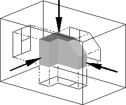
Increasing the focal length and distance of the camera to infinity in a perspective projection results in an orthographic projection.
Orthographic projection is a means of representing a three-dimensional (3D) object in two dimensions (2D). It is a form of parallel projection, where the view direction is orthogonal to the projection plane. It is further divided into multiview orthographic projections and axonometric projections.
Orthographic projection corresponds to a perspective projection with a hypothetical viewpoint—e.g., one where the camera lies an infinite distance away from the object and has an infinite focal length, or "zoom".
[edit] Multiview orthographic projections

An example of an multiview orthographic drawing from a US Patent (1913), showing two views of the same object. Third angle projection is used.

An orthographic three-view of a
tenor trombone, showing (from left to right) a
birds-eye view, a front view (facing the bell), and a side view (from right)

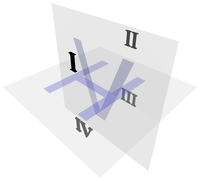
Gaspard Monge's four quadrants and two planes.
With multiview orthographic projections, up to six pictures of an object are produced, with each projection plane parallel to one of the coordinate axes of the object.[1]
The views are positioned relative to each other according to either of two schemes: first-angle or third-angle projection. In each, the appearances of views may be thought of as being projected onto planes that form a 6-sided box around the object.
[edit] Quadrants in descriptive geometry
Modern orthographic projection is derived from Gaspard Monge's descriptive geometry. Monge defined a reference system of two viewing planes, horizontal H ("ground") and vertical V ("backdrop"). These two planes intersect to partition 3D space into 4 quadrants, which he labeled:
- I: above H, in front of V
- II: above H, behind V
- III: below H, behind V
- IV: below H, in front of V
These quadrant labels are the same as used in 2D planar geometry, as seen from infinitely far to the "left", taking H and V to be the X-axis and Y-axis, respectively.
The 3D object of interest is then placed into either quadrant I or III (equivalently, the position of the intersection line between the two planes is shifted), obtaining first- and third-angle projections, respectively. Quadrants II and IV are also mathematically valid, but their use would result in one view "true" and the other view "flipped" by 180° through its vertical centerline, which is too confusing for technical drawings.
Monge's original formulation uses two planes only, and obtains the top and front views only. The addition of a third plane to show a side view (either left or right) is a modern extension. The terminology of quadrant is a mild anachronism, as a modern orthographic projection with three views corresponds more precisely to an octant of 3D space.
[edit] First-angle projection
In first-angle projection, the object is conceptually located in quadrant I, i.e. it floats above and before the viewing planes, the planes are opaque, and each view is pushed through the object onto the plane furthest from it. (Mnemonic: an "actor on a stage".) Extending to the 6-sided box, each view of the object is projected in the direction (sense) of sight of the object, onto the (opaque) interior walls of the box; that is, each view of the object is drawn on the opposite side of the box:
A two-dimensional representation of the object is then created by "unfolding" the box, to view all of the interior walls:
This produces two plan views and four side views:
[edit] Third-angle projection
In third-angle projection, the object is conceptually located in quadrant III, i.e. it lurks below and behind the viewing planes, the planes are transparent, and each view is pulled onto the plane closest to it. (Mnemonic: a "shark in a tank", esp. that is sunken into the floor.) Using the 6-sided viewing box, each view of the object is projected opposite to the direction (sense) of sight, onto the (transparent) exterior walls of the box; that is, each view of the object is drawn on the same side of the box. The box is then unfolded to view all of its exterior walls.
[edit] Additional information
First-angle projection is as if the object were sitting on the paper and, from the "face" (front) view, it is rolled to the right to show the left side or rolled up to show its bottom. It is standard throughout Europe and Asia.
Third-angle is as if the object were a box to be unfolded. If we unfold the box so that the front view is in the center of the two arms, then the top view is above it, the bottom view is below it, the left view is to the left, and the right view is to the right. It is standard in USA and Canada.
Both first-angle and third-angle projections result in the same 6 views; the difference between them is the arrangement of these views around the box.
A great deal of confusion has ensued in drafting rooms and engineering departments when drawings are transferred from one convention to another. On engineering drawings, the projection angle is denoted by an international symbol consisting of a truncated cone, respectively for first-angle (FR) and third-angle (US):

The 3D interpretation of the symbol can be deduced by envisioning a solid truncated cone (Mnemonic: a "gift-wrapped megaphone"), standing upright with its large end on the floor and the small end upward. The top view is therefore two concentric circles ("donut"). In particular, the fact that the inner circle is drawn with a solid line instead of dashed disambiguates this view as the top view, not the bottom view.
- In first-angle projection, the "top" view is pushed down to the floor, and the "front" view is pushed back to the rear wall; the intersection line between these two planes is therefore closest to the large end of the cone, hence the first-angle symbol shows the cone with its large end open toward the donut.
- In third-angle projection, the "top" view is pulled up to the ceiling, and the "front" view is pulled forward to the front wall; the intersection line between the two planes is thus closest to the small end of the cone, hence the third-angle symbol shows the cone with its large end away from the donut.
[edit] Multiviews without rotation
Orthographic multiview projection is derived from the principles of descriptive geometry and may produce an image of a specified, imaginary object as viewed from any direction of space. Orthographic projection is distinguished by parallel projectors emanating from all points of the imaged object and which intersect a plane of projection at right angles. Above, a technique is described that obtains varying views by projecting images after the object is rotated to a desired position.
Descriptive geometry customarily relies on obtaining various views by imagining an object to be stationary, and changing the direction of projection (viewing) in order to obtain the desired view.
See Figure 1. Using the rotation technique above, note that no orthographic view is available looking perpendicularly at any of the inclined surfaces. Suppose a technician desired such a view to, say, look through a hole to be drilled perpendicularly to the surface. Such a view might be desired for calculating clearances or for dimensioning purposes. To obtain this view without multiple rotations requires the principles of Descriptive Geometry. The steps below describe the use of these principles in third angle projection.
- Fig.1: Pictorial of imaginary object that the technician wishes to image.
- Fig.2: The object is imagined behind a vertical plane of projection. The angled corner of the plane of projection is addressed later.
- Fig.3: Projectors emanate parallel from all points of the object, perpendicular to the plane of projection.
- Fig.4: An image is created thereby.
- Fig.5: A second, horizontal plane of projection is added, perpendicular to the first.
- Fig.6: Projectors emanate parallel from all points of the object perpendicular to the second plane of projection.
- Fig.7: An image is created thereby.
- Fig.8: A third plane of projection is added, perpendicular to the previous two.
- Fig.9: Projectors emanate parallel from all points of the object perpendicular to the third plane of projection.

- Fig.10: An image is created thereby.
- Fig.11: A fourth plane of projection is added parallel to the chosen inclined surface, and per force, perpendicular to the first (Frontal) plane of projection.
- Fig.12: Projectors emanate parallel from all points of the object perpendicularly from the inclined surface, and per force, perpendicular to the fourth (Auxiliary) plane of projection.
- Fig.13: An image is created thereby.
- Fig.14-16: The various planes of projection are unfolded to be planar with the Frontal plane of projection.
- Fig.17: The final appearance of an orthographic multiview projection and which includes an "Auxiliary view" showing the true shape of an inclined surface.
[edit] Pictorials
-
Within orthographic projection there is an ancillary category known as Pictorials. Pictorials show an image of an object as viewed from a skew direction in order to reveal all three directions (axes) of space in one picture. Orthographic pictorial instrument drawings are often used to approximate graphical perspective projections, but there is attendant distortion in the approximation. Because pictorial projections innately have this distortion, in the instrument drawing of pictorials, great liberties may then be taken for economy of effort and best effect. Orthographic pictorials rely on the technique of axonometric projection ("to measure along axes").
[edit] See also
[edit] References
[edit] External links


